With ray tracing being done from the eye much more now, this is a lesson to be relearned: code’s better and life’s easier if the center of the pixel is the fraction (0.5, 0.5). If you are sure you’re doing this right, great; move on, nothing to see here. Enjoy this instead.
Mapping the pixel center to (0.5,0.5) is something first explained (at least first for me) in Paul Heckbert’s lovely little article “What Are the Coordinates of a Pixel?”, Graphics Gems, p. 246-248, 1990.
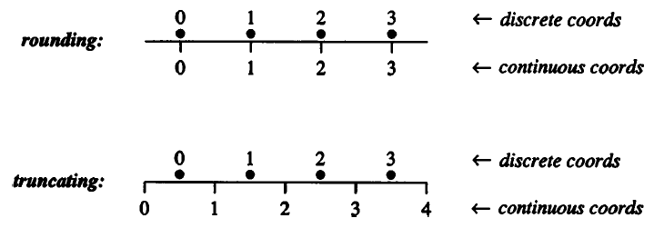
That article is hard to find nowadays, so here’s the gist. Say you have a screen width and height of 1000. Let’s just talk about the X axis. It might be tempting to say 0.0 is the center of the leftmost pixel in a row, 1.0 is the center next to it, etc. You can even then use rounding, where a floating-point coordinate of 73.6 and 74.4 both then go to the center 74.0.
However, think again. Using this mapping gives -0.5 as the left edge, 999.5 as the right. This is unpleasant to work with. Worse yet, if various operators such as abs() or mod() get used on the pixel coordinate values, this mapping can lead to subtle errors along the edges.
Easier is the range 0.0 to 1000.0, meaning the center each pixel is at the fraction 0.5. For example, integer pixel 43 then has the sensible range of 43.0 to 43.99999 for subpixel values within it. Here’s Paul’s visualization:
OpenGL has always considered the fraction (0.5,0.5) the pixel center. DirectX didn’t, at first, but eventually got with the program with DirectX 10.
The operations for proper conversion from integer to float pixel coordinates is to add 0.5; float to integer is to use floor().
This is old news. Everyone does it this way, right? I bring it up because I’m starting to see in some ray tracing samples (pseudo)code like this for generating the direction for a perspective camera:
 float3 ray_origin = camera->eye;
 float2 d = 2.0 *
     ( float2(idx.x, idx.y) /
       float2(width, height) ) - 1.0;
 float3 ray_direction =
     d.x*camera->U + d.y*camera->V + camera->W;
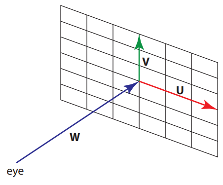
The vector idx is the integer location of the pixel, width and height the screen resolution. The vector d is computed and used to generate a world-space vector by multiplying it by two vectors, U and V. The W vector, the camera’s direction in world space, is added in. U and V represent the positive X and Y axes of a view plane at the distance of W from the eye. It all looks nice and symmetric in the code above, and it mostly is.
The vector d is supposed to represent a pair of values from -1.0 to 1.0 in Normalized Device Coordinates (NDC) for points on the screen. However, the code fails. Continuing our example, integer pixel location (0,0) goes to (-1.0,-1.0). That sounds good, right? But our highest integer pixel location is (999,999), which converts to (0.998,0.998). The total difference of 0.002 is because this bad mapping shifts the whole view over half a pixel. These pixel centers should be 0.001 away from the edge on each side.
The second line of code should be:
    float2 d = 2.0 *
        ( ( float2(idx.x, idx.y) + float2(0.5,0.5) ) /
            float2(width, height) ) - 1.0;
This then gives the proper NDC range for the centers of pixels, -0.999 to 0.999. If we instead transform the floating-point corner values (0.0,0.0) and (1000.0,1000.0) through this transform (we don’t add the 0.5 since we’re already in floating point), we get the full NDC range, -1.0 to 1.0, edge to edge, proving the code correct.
If the 0.5 annoys you and you miss symmetry, this formulation is elegant when generating random values inside a pixel, i.e., for when you’re antialiasing by shooting more rays at random through each pixel:
    float2 d = 2.0 *
        ( ( float2(idx.x, idx.y) +
                float2( rand(seed), rand(seed) ) ) /
            float2(width, height) ) - 1.0;
You simply add a random number from the range [0.0,1.0) to each integer pixel location value. The average of this random value will be 0.5, at the center of the pixel.
Long and short: beware. Get that half pixel right. In my experience, these half-pixel errors would occasionally crop up in various places (cameras, texture sampling, etc.) over the years when I worked on rasterizer-related code at Autodesk. They caused nothing but pain on down the line. They’ll appear again in ray tracers if we’re not careful.