You’re mapping a latitude-longitude texture on to a sphere. Pretty straightforward, right? Compute the UV coordinates at the vertices and let the rasterizer do the work. The only problem is that you can’t get exactly the right answer at the poles. Part of the problem is that getting a good U value at each pole is problematic: U is essentially undefined. It’s like asking what longitude you’re at when you’re sitting at the north pole – you can take your pick, since none is correct.
One way around this is to look at the other vertices in the triangle (i.e., those not at the pole) and average the U values they have. This gives a tessellation at the north pole something like this:
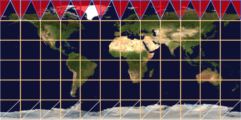
What’s interesting about this tessellation is that it leaves out half of the horizontal strip of texture near the pole. The sawtooth of triangles will display one half of the texture in this strip, but will not display the triangles covered in red. Even if you form these triangles, adding them to the mesh, they won’t appear. Recall that all points along the upper edge of the texture are located at the same position in world space, the north pole of the model itself. So any red triangles added will collapse; they’ll have zero area, as their two points along the top edge are co-located.
I show a different tessellation along the bottom strip of the texture, a more traditional way to generate the UV coordinates and triangles. Again, all the triangles with edges along the bottom of the texture will collapse to zero area, and half of the texture in the strip will not be rendered. The triangles that are rendered here are somewhat arbitrary – at least the triangles along the top edge have a symmetry to them.
There are two ways I know to improve the rendering. One is to tessellate more: the more lines of latitude you make, the smaller the problem areas at the poles become. The artifacts are still there, but contained in a smaller area. The other, ultimate solution is that you could compute the UV location per pixel, not per vertex.
That works for texturing, if you can afford to fold the spherical mapping into the pixel shader. However, this problem isn’t limited to spheres, and isn’t limited to textures. Another example is the cone and having a normal per vertex. This is a common object, but is surprisingly messy. For a cone pointing up you typically make a separate vertex for each triangle meeting at the tip, with a separate normal. This is similar to the uppermost strip for the sphere mapping above: the normal points out in a direction somewhere between the two bottom normals for the triangle in the cone.
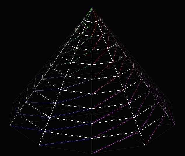
However, you have the same sort of interpolation problem! Here’s a cone with a tessellation of 40 vertices around the top and bottom edges:
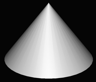
From triangle to triangle along the side of the cone, you have normals smoothly interpolating along the bottom of the cone. Moving across a vertical edge near the tip, you have sudden shifts in the normal’s direction as you go from one normal to another. Each zero-area triangle that is formed by two points touching the pole is what “causes” the discontinuity in shading when crossing an edge.
If you start to add “lines of latitude”, to vertically tessellate the surface, things improve. Here are cones with two strips of triangles, three strips, then ten strips:

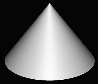

It’s interesting to me that the first image, two strips of triangles, doesn’t fully improve the bottom part of the cone. Even though there are no zero-area triangles and so the normal is the same for each vertex in this area, the normals change at different rates across the surface and our eyes pick this up as Mach banding of a sort. Three strips gives three bands of poor interpolation, and so on. With ten bands things look good, at least for this lighting and amount of specularity. Increasing the tessellation gets us closer and closer to the ideal per-pixel computation.
Here are some images of the cone mapping to show the discontinuities. The first gives a low tessellation: 10 vertices around, no tessellation vertically
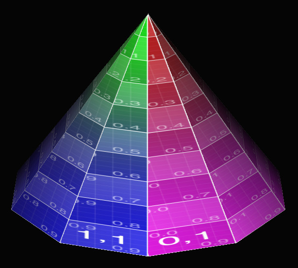
Half of the texture is missing on each face of the cone. If you increase the vertical tessellation, like so:
You get this:
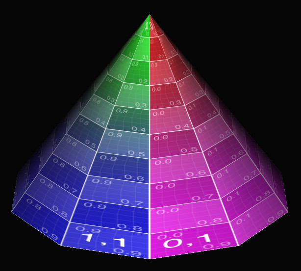
It’s better, but there’s still a dropout at the tip (it should say “1,0 | 0,0”), plus you can see the lines on the surface are not straight – the vertical lines on the faces wobble. Each quadrilateral is a trapezoid, so using two triangles for this mapping doesn’t match it all that well.
If you increase the tessellation in both directions, you get closer still to a per pixel mapping, the correct answer:
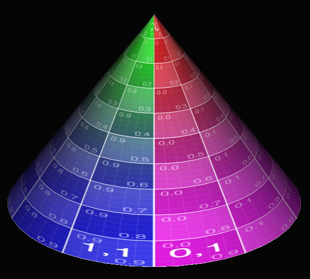
This tessellation is 40 points around, 10 points from bottom to top. The very tip still has half its information missing, but otherwise things look reasonable. Cranking the resolution up to 50 around and 50 from bottom to top mostly cleans up the tip (ignoring the lack of high-quality texture sampling):

This is an old phenomenon, but still a surprising one, at least to me. We’re used to tessellating any higher-order surface into triangles for rasterization or ray tracing. Usually I increase tessellation just to capture geometric details, not normal or texture interpolation. You would think it would be possible to easily set up triangles in such a way that relatively simple mappings would not have problems such as these. You basically want something more like a quadrilateral mapping, where the left edge of the triangle is using, say, U = 0.20 along its edge and the right edge uses U = 0.30. The problem is that the point at the tip has a U of say 0.25, so both edges interpolate from there.
I should note that this problem is solvable by messing with the mappings themselves. For example, you could instead use a different texture and a cube map projected onto a sphere to solve that case, which would also decrease distortion and so require less texture resolution overall.
Woo, Pearce, and Ouellette have a lovely old paper about this and other common rendering bugs and their solutions. They reference a paper by Nelson Max from 1989, “Smooth Appearance for Polygonal Surfaces” for using C1 continuity. This doesn’t seem easy to do on the GPU without a lot of extra data. Has anyone tried solving this general problem, of treating two triangles as a quadrilateral mapping? I don’t really need to solve this problem right now, I just think it’s interesting, something that’s doable in a pixel shader in some way. I’m hoping someone’s created an elegant solution.
Update: and I got a solution of sorts. Thanks to Tom Forsyth for getting the ball rolling on Twitter. Nathan Reed’s post on this topic talks about setup, Iñigo Quílez talks about performing bilinear interpolation in the shader and gives a ShaderToy demo. However, these seem a bit apples and oranges: Nathan is working with projective interpolation, Inigo is working with equi-spaced bilinear interpolation – they’re different. See page 14 on of Heckbert’s master’s thesis, for example.
Another update: Jules Bloomenthal notes how his barycentric quad rasterization work fixes cones.
Great article! As you noted, sometimes re-tessellating with a different scheme can help (e.g., using a subdivided icosahedron for a sphere, rather than latitude/longitude lines). There are also times when adding more triangles makes things worse, and the more you subdivide the worse it gets! An example is in http://www.glassner.com/wp-content/uploads/2014/04/CG-CGA-PDF-97-09-Perils-of-Problematic-Parameterization-Sep97.pdf